220 Volts to the Present: From life threatening danger to safety
During the late 19th century and into the early 20th century, Märklin toy trains used one of three power sources – clockwork motors, live steam and electricity. In time, the first two methods with their inherent limitations were displaced, but not entirely replaced, by electric motors. So it was that in 1895 Märklin offered its first electric motor driven toy locomotives. These trains were, for all practical purposes, connected through a suitable (variable) resistor directly to the residential 110 or 220 volt AC or DC network. There were two approaches. Not ideal but one approach was less dangerous than the other.
Two Approaches
There were two approaches. Figure 1 shows the direct connection. The left part of the diagram shows two parallel-connected carbon filament lamps and a variable resistor. The second of the two schematics is the locomotive with two series- connected headlights. Even rudimentary study reveals the danger inherent in this approach.
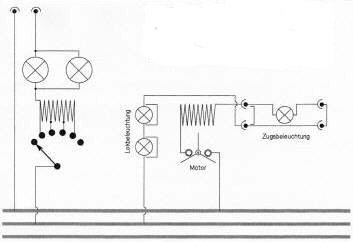
Schematic diagram of direct connection to residential 110/220-volt system.
For all practical purposes these early electric toy trains were connected directly to the 110/220-volt AC residential service. The only electrical devices between the track and the electrical outlets were two carbon filament light bulbs and a variable resistor with several taps. These bulbs have to be handled with some care since they are sensitive to mechanical shock. So, why carbon filament lamps? Tungsten filament lamps did not appear until about ten years later.

High voltage regulator with two carbon filament lamps.
While tungsten filament lamps are more rugged, their electrical resistance varies momentarily from the moment they are energized to the point where they are lit. This microsecond interval affects the model train. When turned on, the train is very likely going to take off at full speed.
Here’s why. The cold resistance of tungsten-filament lamps is about 1/15th the hot-filament resistance when the lamp is operating. For example, a 100-Watt, 120-volt lamp has a resistance of 144 ohms when lit, but the cold resistance is much lower at about 9.5 Ohms.
Carbon filament lamps have the opposite characteristic. The resistance of a carbon filament is higher when it is cold than when it is operating. In the case of a 240 Volt, 60 Watt carbon filament lamp, the resistance of the filament when at operating temperature is 960 Ohms, but increases to about 1500 Ohms when cold.
The second of the two approaches, Figure 2, shows how much safer it is. The use of the transformer with its built-in speed controller effectively isolates the train tracks from the 110/220-volt AC house network. More about this follows.

Schematic diagram for system using a transformer.
Danger lurked
But back to the direct connection approach. Before the First World War there were various commercial DC systems in use for residential electric power distribution. In most cases these systems did not use any sort of grounding. While receiving a shock from a DC system can be most unpleasant, it is not as nearly life threatening as it would be from an improperly grounded AC system. The various DC systems were gradually replaced after the First World War with AC systems that made use of grounding one of the two conductors. Grounding was via water supply pipes and other metal appliances. Thus, if while righting a derailed locomotive or car, the model train player touched a radiator, let’s say, he could conceivably receive a very, very nasty shock.
Improvements were needed
Something had to be done. Märklin began by offering a version of the “plug and socket” system that became a trademark. This ensured correct wiring, provided, of course, that the directions were followed. Yet, the metallic contacts of the speed controller posed a danger. Then, of course, there were the all-metal trains themselves.
It was not until 1925 that a major step forward was taken with the introduction of what effectively was an isolation transformer. See Fig. 2. Märklin took the opportunity to publish the following in their 1925 catalog, “The train set should be placed on a wooden or linoleum covered floor. Particular attention should be paid to not locating the train set near any radiators, gas or water pipes.” Märklin further offered this advice. “In case of a short, the first action should be to immediately shut off power.” While this may be obvious today, it was not necessarily so in the mid-1920s. No other safety improvements were forthcoming until some time in 1926.
Some progress had been made at Märklin because that year the company began to offer some locomotives that operated on 20 volts AC. Still, locomotives for 110 volts DC house current had not been redesigned for the safer low-voltage operation.
The death knell of the directly connected to house current engines came a year later in 1927. The manufacturer Bing commented, “it is imperative that these toy trains be made sufficiently safe to be operated by children without adult supervision.” Märklin chose its words very carefully with this statement, “our new trains do away with the unpleasantries associated with the carbon filament lamp controllers.” Bub, also a toy train manufacturer, had not yet joined the safety chorus in that they continued to offer trains that were connected directly to the residential electrical system though these products were marked – Not to be sold in Germany.
VDE recognizes the danger
In December 1926 the Verband Deutscher Elektrotechniker (VDE), the German Association of Electrical Engineers issued rules and regulations that, effective immediately (January 1, 1927), the manufacturers of toy trains can no longer offer model trains that operate by direct connection to the residential power system. The new products were intended to be in stores by April 1, 1927.
The main points of the new rules were:
- Toy trains and other electric toys cannot operate at voltages over 24 volts.
- Direct connection to 110/220-volt systems is not permitted.
These requirements brought about a fundamental change in designing and manufacturing of electrically operated toys.
Connection devices
The direct connection devices with their incandescent lamps (the lamps were wired in parallel) and the built-in metallic resistor were designed to accept three different wattage lamps depending on what locomotive was to be operated. Lamps ranging from 30 to 180 W were used. These devices were used for AC and DC residential service since the locomotives used universal motors. The motors operated on 30 to 60 volts.
Model trains built to the newly mandated VDE requirements could only use newly developed speed regulators that did not have any connection to the residential power grid; in other words the new speed regulators were for use only in secondary, low voltage circuits. The net result was that transformers and DC-to-DC motor- generators came into use.
Then parents shopping for their budding model railroaders had to be able to tell the hobby store whether the house was on AC or DC power as well as what locomotive was to be unwrapped at Christmas. Households on AC power would buy a transformer and a regulator to match the Christmas locomotive. Similarly in DC homes, a matching DC-to-DC motor-generator and speed controller would have to be bought. Since there were so many different AC and DC houses, no fewer than 21 different transformers, motor-generators and controllers were available from Märklin.
Low voltage systems
Märklin did not neglect potential customers living in areas without electric service. The company offered several locomotives that operated by either flashlight batteries or lead-acid storage batteries that were not without their potential danger. To activate the lead-acid battery the user, hopefully an adult, had to procure the necessary concentrated sulfuric acid.
The company Meiser & Mertig offered a low voltage system consisting of battery using a dichromate (probably sodium or potassium dichromate) electrolyte solution. Running time of the two small cars around a simple oval was approximately 30 minutes. Just as high voltages were used to power trains, the chemical energy sources were equally dangerous in their own way.

Chromate solution
For those households with DC mains, Märklin also offered DC-to-DC motor- generators for operation of its high voltage DC. A motor-generator is a rotary device that looks much like a fractional horse- power electric motor. It consists of an electric motor mechanically coupled to an electric generator. The motor runs on the electrical input current while the generator creates the electrical output power. In many German houses the supply was DC but the actual value was not constant throughout Germany.
Editor’s note: DC-to-DC motor-generators (dynamotors) were widely used by the aircraft industry well into the 1940s. The basic aircraft electrical system was 24 volts DC but radios, radar and other airborne electronic devices required anywhere from 90 volts DC and more for their operation. At the time only way to deal with that was by means of high voltage dynamotors.
Changeover
The law that forbade the sale of toy trains operating on voltages greater than 24 volts was strictly enforced. Even repair- ing of high voltage (direct connection engines) was discouraged and the owner of such equipment had to sign a legal release absolving Märklin of any and all legal action on the part of the owner.
Customers were encouraged to update to the far safer transformer control and Märklin made every effort to accommodate them. The firm used a symbol to identify the operating voltage of its motors. A yellow lightning flash was for 110/220 volts AC, a green flash indicated 4 volts DC and a red flash was for 20 volts AC.
The changeover to the vastly safer 20-volt system offered by Märklin starting in the late 1920s marked a quantum leap forward in the manufacturing and enjoyment of toy and model trains.
Sources:
- “Vom Starkstrom zum 20 Volt- System,” F. Rinderknecht, November 2000, Website www.tinplatefan.ch. (in German).
- “Wertanlage Märklin,” Joachim Koll, Reinhard Schiffmann. Augustus Verlag, Augsburg, 1996, ISBN 3-8034-0361-7.